
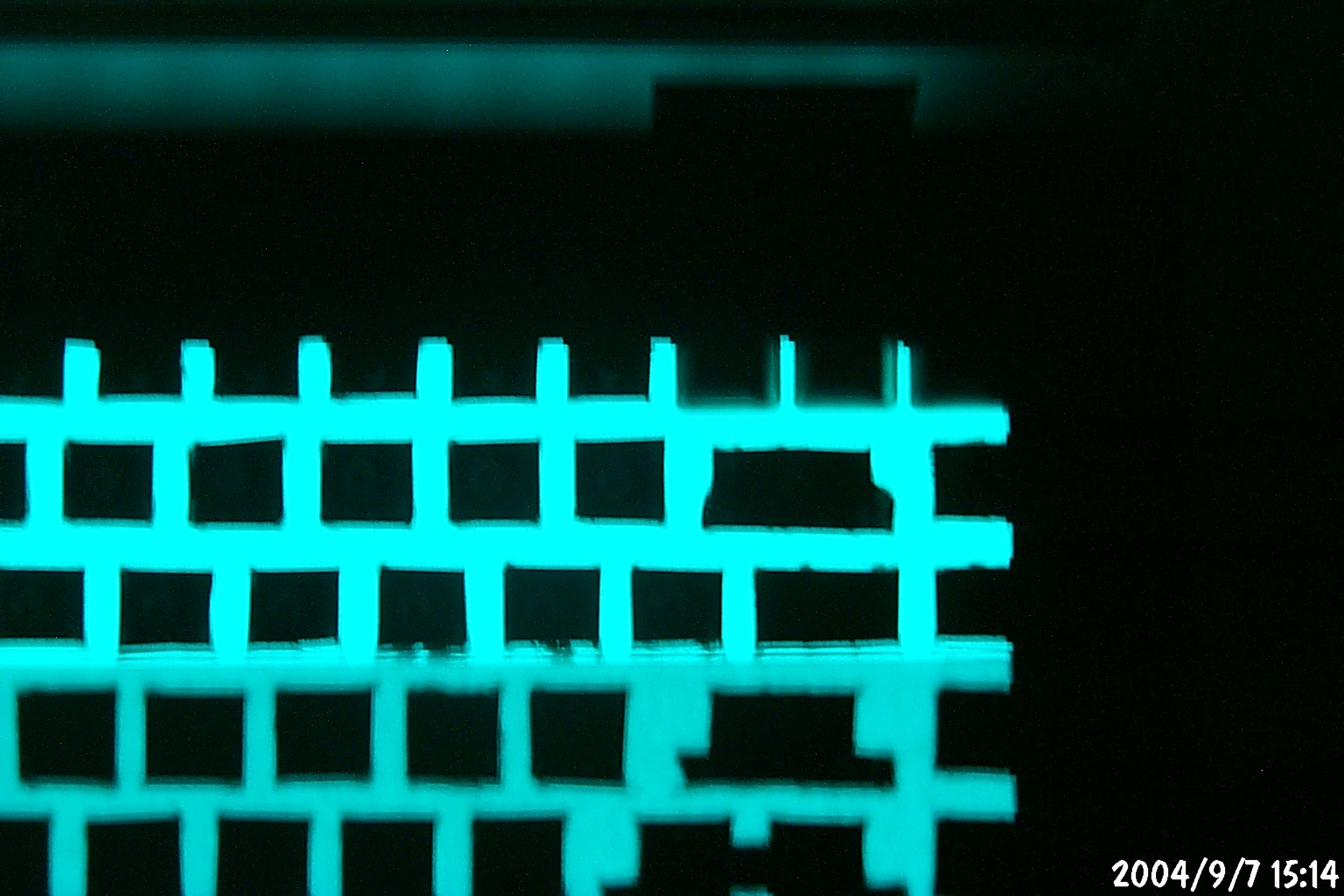
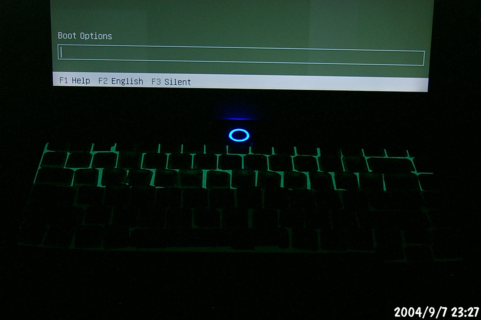
Aside from the lack of clearance (when the wire was routed under the keys, you couldn't press the keys down any more), you can see that the illumination is very uneven and doesn't make the lettering on the keytops legible.
Since the Asus M6 notebook series comes with transparent keys, I thought it would be a bright idea to try to backlight them. I spend a lot of time working on the computer without other room lights on, and this would make my life a lot easier if I could see the keyboard better. And buying a $10 USB light just seemed like too mundane a solution.
I read about some other folks successfully using EL wire to light up
their desktop keyboards, so I gave this a shot. The result wasn't very
nice on the Asus M6 keyboard though, because the key travel is so short
there isn't enough clearance for the wire. Here's a view of that first
attempt (click on the images for the full-size view):
Aside from the lack of clearance (when the wire was routed under the keys,
you couldn't press the keys down any more), you can see that the
illumination is very uneven and doesn't make the lettering on the
keytops legible.
So my next idea was to try a sheet of EL material instead. I ordered
a 2 foot x 6 inch strip of split-electrode sheet from
Luminous Film and a
Supertex
EL inverter from Mouser Electronics
to drive it. Unfortunately, I burned out the SuperTex inverter within
about 3 minutes of using it on my test power supply. It took over a
month to get a replacement from SuperTex. Also, I originally ordered
their HV830DB1 kit; the replacement they sent was an HV823DB1 which
has a lower output voltage and hence is slightly dimmer. Here's a
shot of the dead HV830DB1, I think the smear in the lower right
corner of the circuit board is the remains of the capacitor exploding.

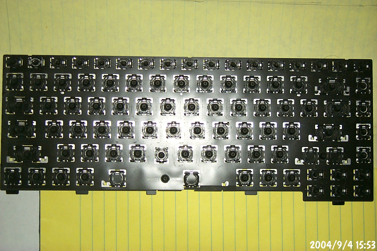
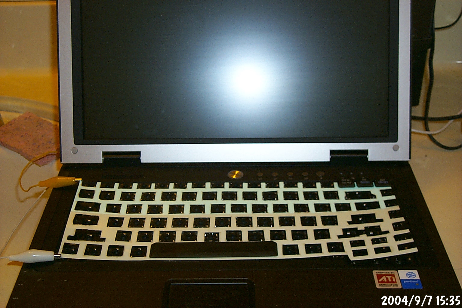
Anyway, with the arrival of the new HV823DB1 I set to work again. First I
removed the keyboard from the laptop and removed all of the keycaps. Then
I started to trace it so I could begin cutting out a template for the EL
sheet, but I decided to just print the photo of the keyboard and use that
as the template.
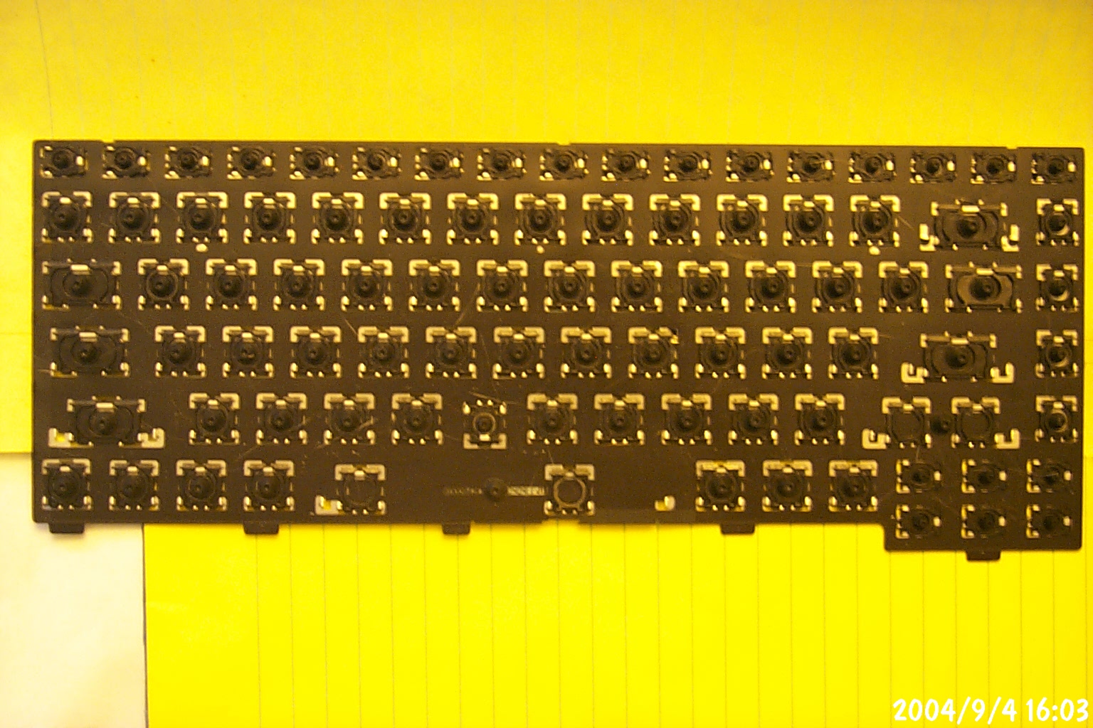
The second shot is the same, with no flash. In hindsight I probably
should have tried to lay this out on my scanner and use that instead,
although the rubber keysprings might have interfered with that...
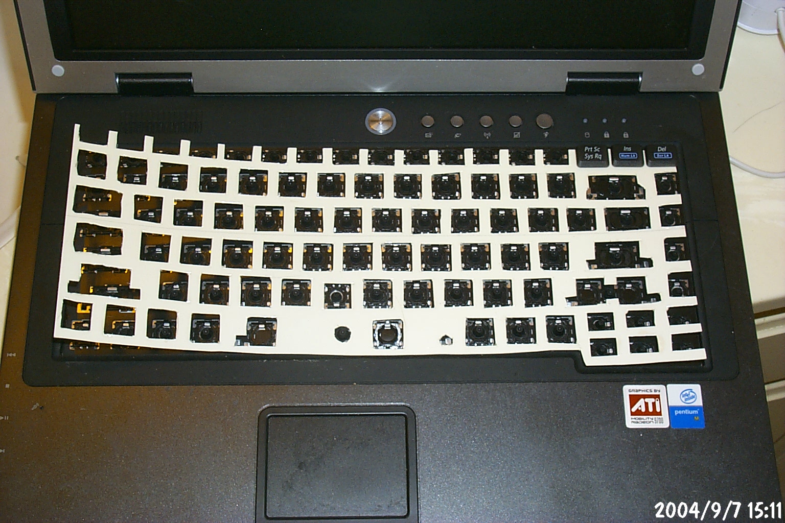
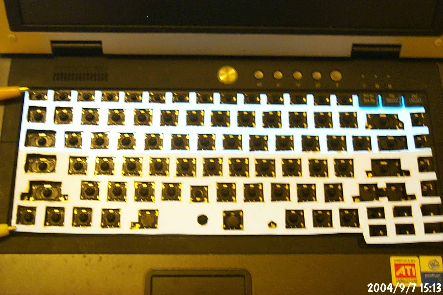
After many hours of sweating and cursing using various sizes of
Xacto knives, I managed to cut out a piece of EL sheet to
lay over the keyboard. In these two photos, the PrtSc,
Insert, and Delete keys are attached in the top right corner.
In the second photo, the EL power is turned on.
For reference, the Asus M6 keyboard is exactly 30cm long. The
width is mostly 10.7cm with an extension to 11.5cm for the cursor
keys. The split-electrode EL sheet is extremely thick due to multiple
layers of lamination encasing it. Small hobby knives are just not
the ideal tool for this job...
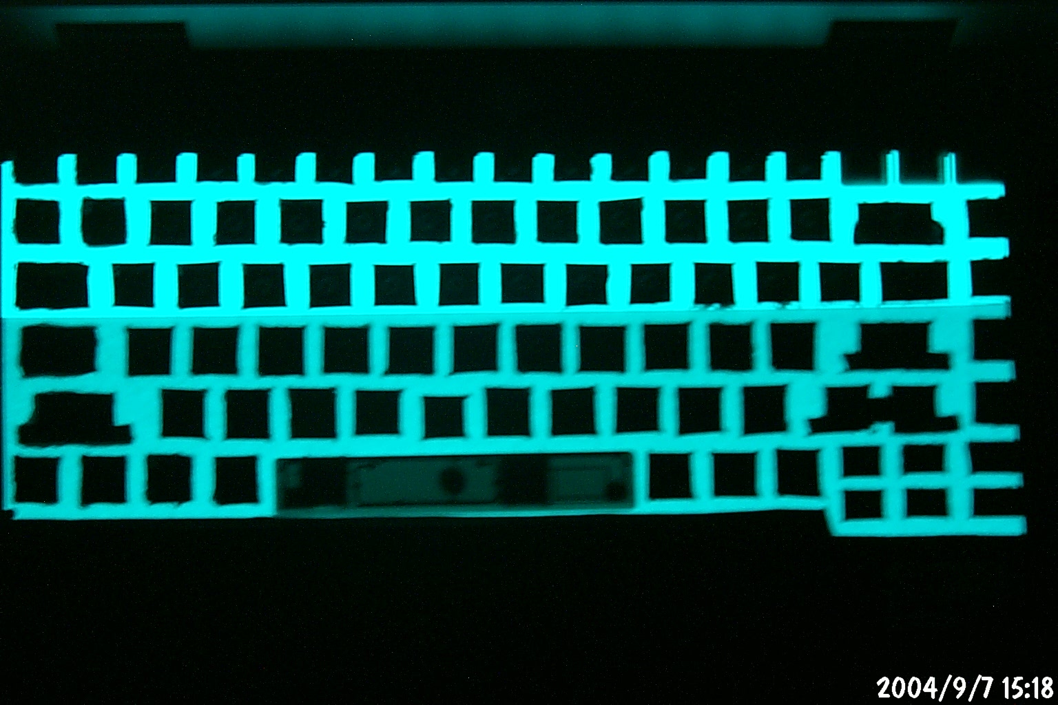
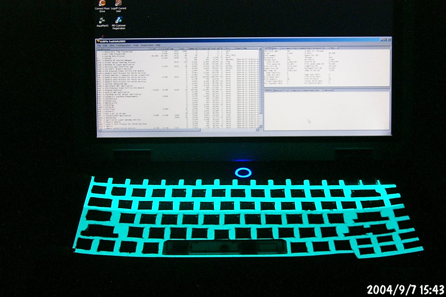
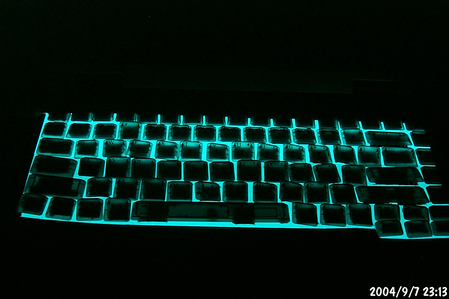
Here are some shots of the EL sheet in the dark...

Some of these are pretty blurry because I wasn't using a tripod.
I set up my tripod for the later photos...

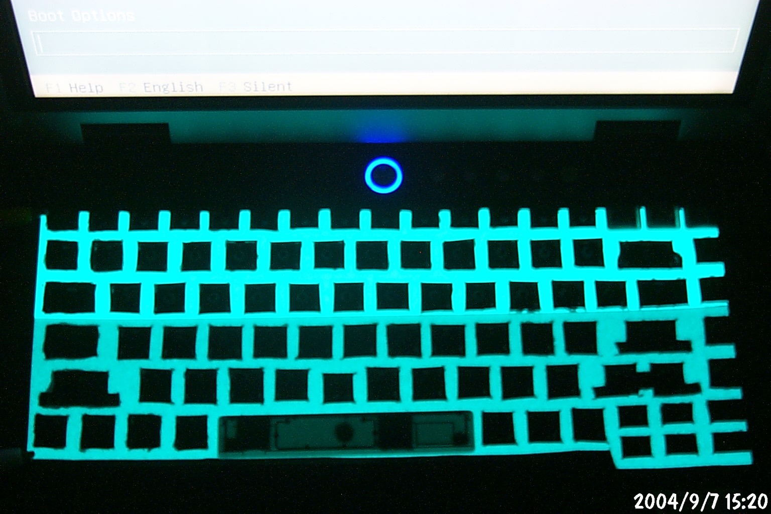
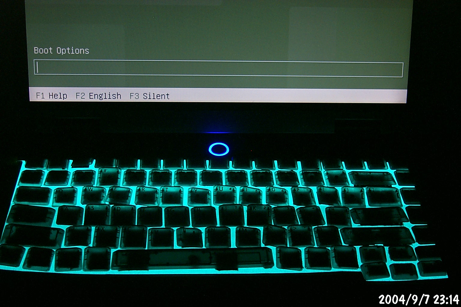
Another pair of lit shots with the backlight switched off
and then switched on. Also I've added the space bar to
the keyboard.

Shots of the keyboard in the dark, now using my tripod...


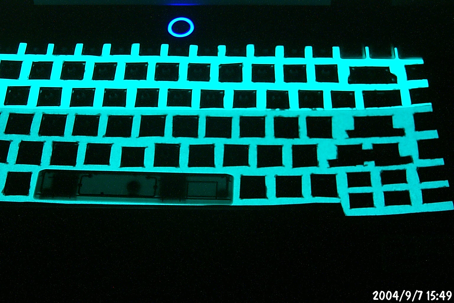


So the big problem remains - as you can see from looking at the PrtSc, Insert, and Delete keys in the top right corner, since I had to cut out holes for the keyswitch mechanisms, the EL sheet doesn't illuminate the keycap lettering at all. So even though there's this nice glow, the keyboard is completely unreadable.
I haven't completely given up yet. I'm trying to find contacts
at Auravision and Asus about having an EL keyboard explicitly
manufactured for the M6N. If that fails, I may try modifying
an existing Eluminx keyboard for the job. If you look at these
two keyboards, it appears they have a similar form factor
(excluding the numeric pad on the Eluminx):

So far I haven't seen one in person, but looking at the photos and
the spec sheet (total length 42cm) I believe the main keyboard area
is only 30cm, which would be the right size. And it has the same
overhang for the cursor pad. It may be awkward since it has no Fn
key, but still it seems to be worth investigating. (After all, if
only the switch matrix is different and the scan codes are still
the same, then the BIOS should interpret everything the same.)
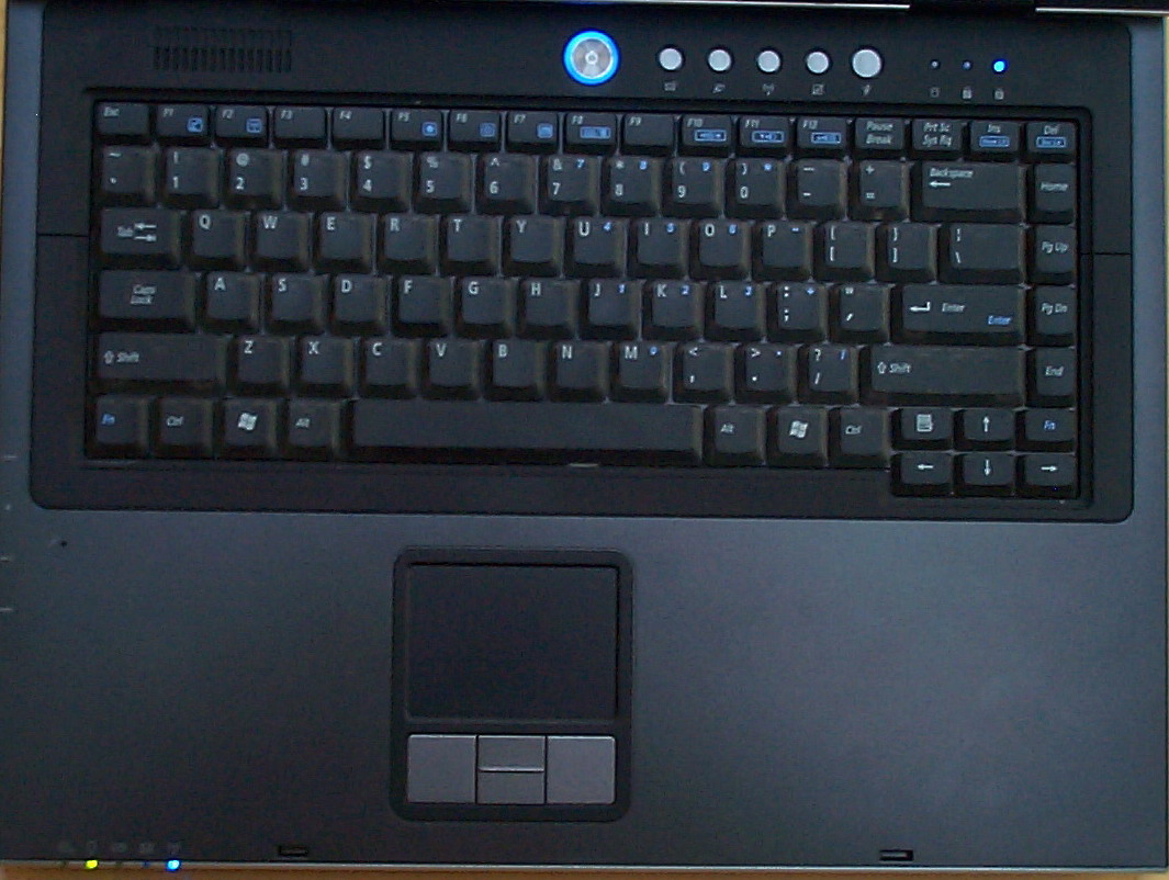
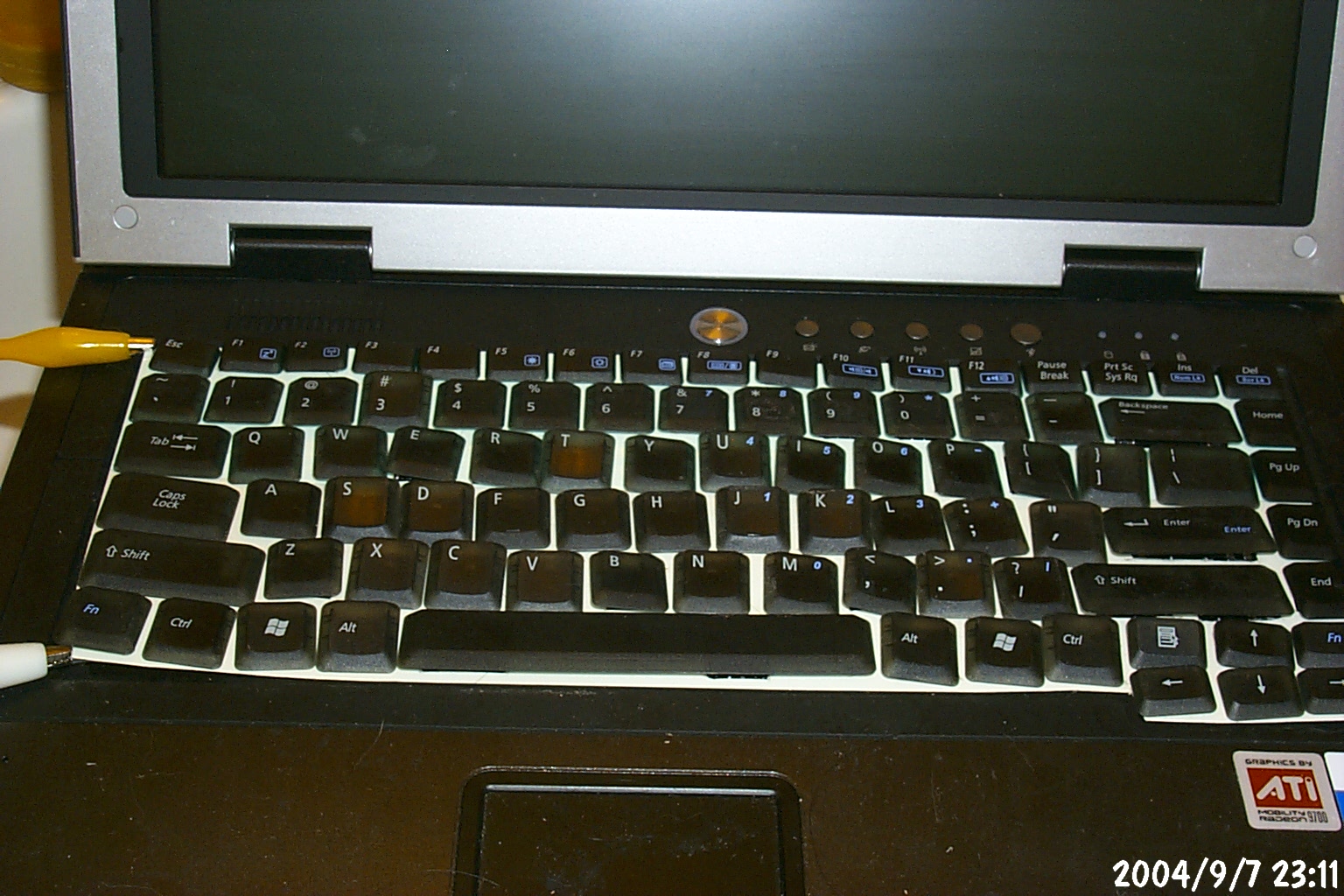
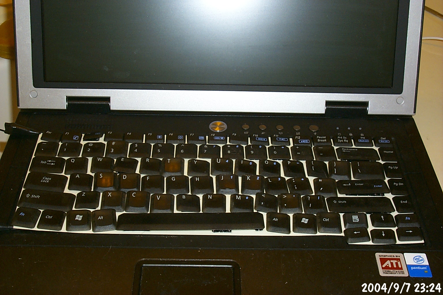
Even though I wasn't able to reattach all the keys while the EL
sheet was mounted, I decided to get a couple shots with all of
the keys sitting on the keyboard. The keys are just resting on
their positions, they are not locked into place, so a few are
sitting crooked in these shots.
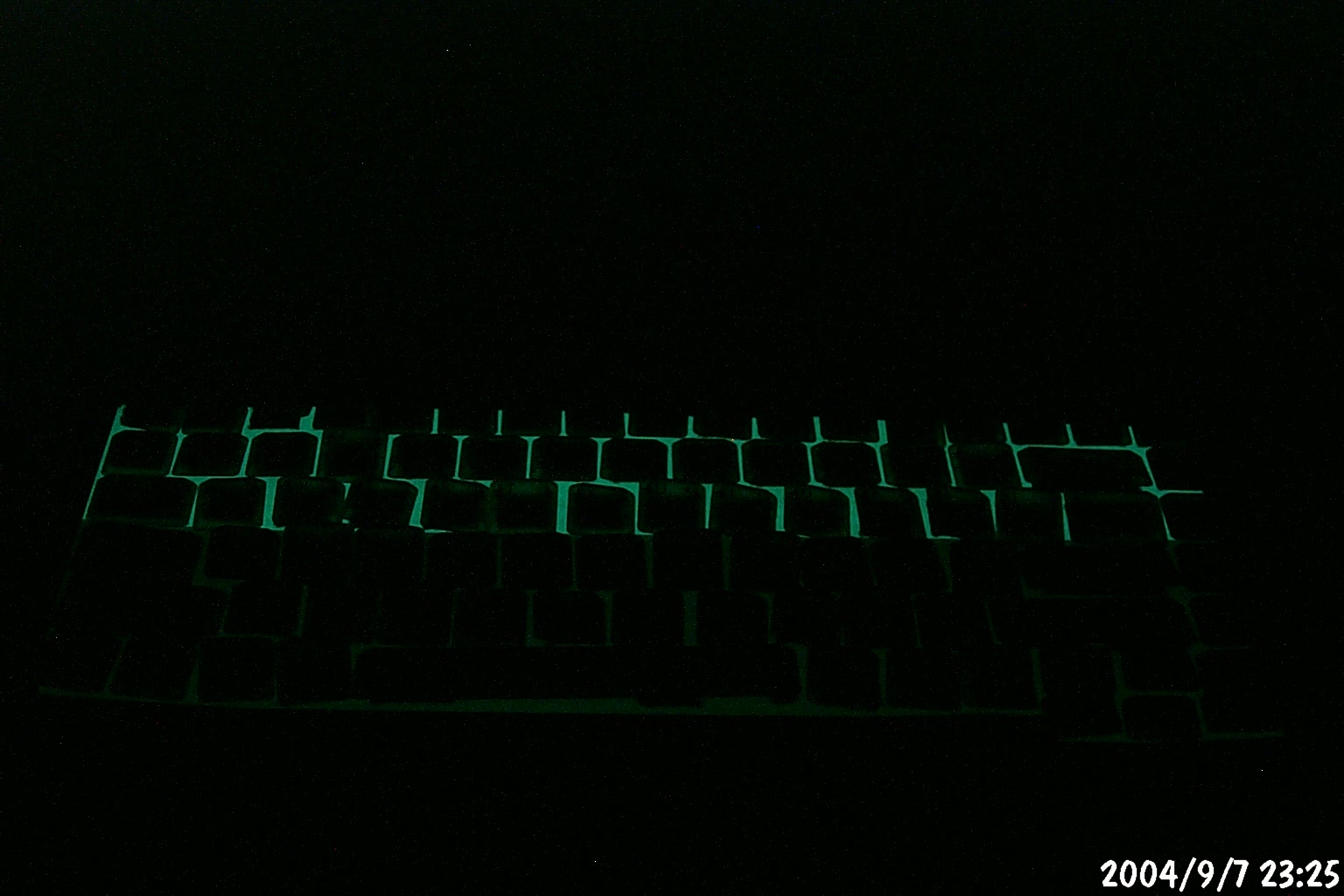
All of the preceding shots were using a separate EL inverter
with a 12V DC supply. The following are actual shots using
the Supertex HV823DB1 driver and a 3VDC input. It is barely noticable
with any room illumination, and it's also incredibly dim even
in the dark.

It occurs to me that I may not need to be able to read the keytops
at all. It may be sufficient just to see the outlines of
the keys; I just need a few landmarks to know where I am on the
keyboard. Still thinking about it...